Branching Bridge
One crossing, a branching edge.
Overview
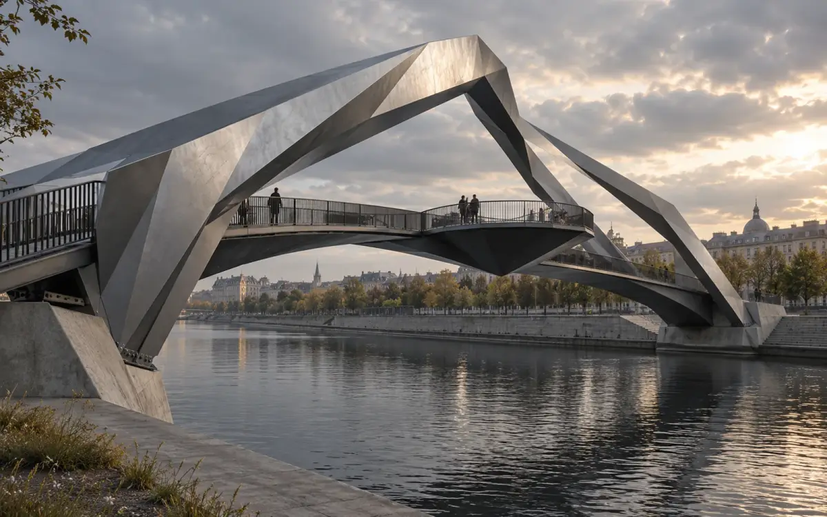
The bridge keeps a direct walking line between two banks and widens one edge into an overlook. Folded steel ribs rise above the timber deck, giving the crossing an asymmetrical profile. The widening gives pedestrians a place to pause beside the through-route; its position and depth must allow people to stop without forcing others into a detour.
The 45 m span and 4.2 m deck width are design targets. Separating the walking surface, branching ribs and bank supports makes their proposed relationships readable. The drawing asks how the expressive upper form could be tied to the deck below, and how the wider edge should be supported. These are questions for the next structural model, rather than results of an optimisation.
Design question
How can a direct crossing also make room for a pause above the water?
- Location
- Two-bank pedestrian crossing scenario
- Client
- Self-initiated Fraktal study
- Team
- Fraktal
- Earlier study
- 2024
How the edge meets the bank
Two bank supports, open waterway
Two bank supports, open waterway
Two bank supports, open waterway
The main deck connects two banks with no intermediate pier in the water.
Schematic design study. It does not verify dimensions or performance.
Deck, frame and bank connections
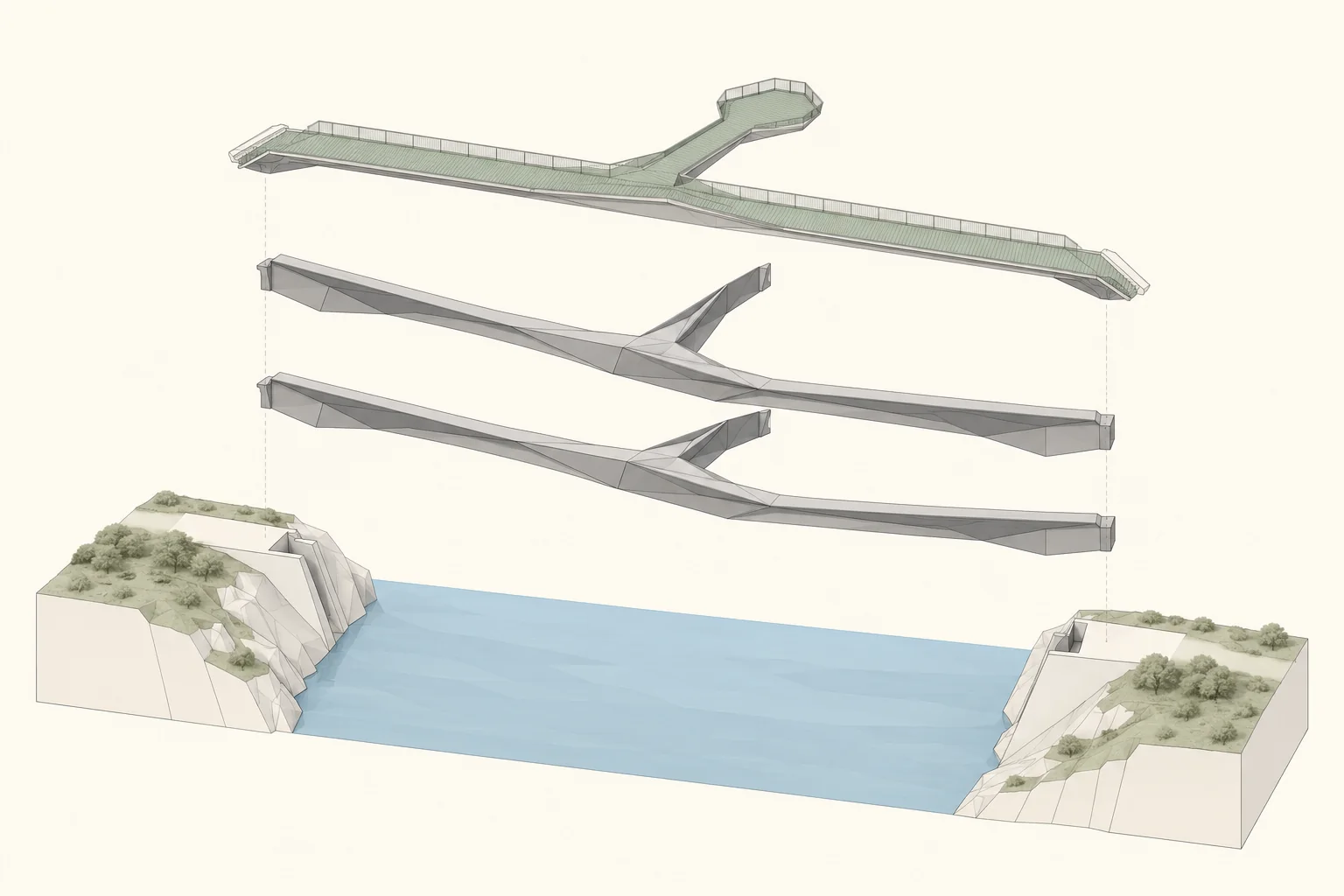
Alongside the above-deck frame shown in the render, this alternative assembly study explores placing faceted members below the walking deck. Separating the layers lets us compare the relationships between deck, frame and banks. Geometry, joints and load path remain questions for the structural model.
 View larger
 - The walking surface
- The deck preserves the crossing line and opens an edge for stopping. The width of that edge must be considered with the route left clear for other pedestrians.
- The branching frame
- Faceted members are shown apart from the deck to examine a possible branching assembly. Their depths, junctions and continuity need to be resolved in a structural model.
- The bank connections
- The crossing meets the ground at two banks. Deck movement, assembly access and the transition from bank path to bridge need to be developed at these junctions.
Design Process
A direct walking line
The main deck continues between the banks while the overlook branches from its edge. Keeping the two uses legible makes the crossing a small public place as well as a route. Approach levels and the clear path through a gathering still need to be resolved.
Branching ribs
A repeated Y-shaped family links the deck to the proposed bank supports. Branch position is considered with the widened edge and the overhead profile. An engineering model must establish whether those branches can form a continuous load path and how asymmetric loading is resisted.
Joints as assembly points
Deck-to-rib junctions connect parts with different fabrication and replacement needs. The timber walking layer is considered separately from the steel frame. Connections need room for assembly, drainage and inspection without becoming barriers on the pedestrian surface.
Questions in conversation
ZHA / Eleftheria Square
At Eleftheria Square, a bridge also forms a public square connected to the surrounding streets. We take the relationship between movement and gathering as a question for this crossing: how much can its edge widen for a pause while keeping the main route direct?
ZHA / Eleftheria Square ↗Drawings & gallery
Compare design states and spatial relationships. Open an image to inspect the details.
Technical details
The concept programme, design inputs and proposed systems.
- Span target
- 45 m
- Deck width target
- 4.2 m
Material Palette
- Folded steel
- Faceted ribs and branching edges.
- Timber decking
- Replaceable walking surface.
- Concrete abutments
- Two clear points of support.
Tools
Plan and section study · Schematic architectural drawings · AI-assisted concept visualization
Infrastructure · Computational design · Concept
Design decisions and limits
Two banks, no intermediate pier
The proposal leaves the waterway free of an intermediate pier. Whether the target span can support this arrangement remains to be established.
Geometry before verification
Branching describes a proposed support hierarchy. It is not yet a calculated or topology-optimised structure.
Next steps
The overlook gains space beside the crossing but makes the deck asymmetric. Widening, rib height and the distribution of supports need to be developed together; a strong silhouette alone cannot settle that relationship. The proposal also leaves the waterway free of an intermediate pier, making the bank connections central to its feasibility.
The next design comparison should examine frame placement above and below the deck, alongside a simple crossing, under the same span and load assumptions. The alternative below-deck assembly diagram opens that comparison; no structural evaluation has been carried out. Deflection, vibration, fatigue, corrosion and flood clearance need assessment alongside accessible approaches, railings and the pedestrian space around the overlook.